How to setup an External Tank with Venting from the Preheat/Constant Level Tank
An external tank is one that is outside of the building containing the oil furnace. This tank is necessary for a few reasons. First you typically will want to store a large quantity of fuel and there is usually more room outside. Most importantly, however, you do not want fumes from the storage tank to get inside the building. Also, the Constant Level/Preheat Tank will generate some fumes when in use as it is preheating the oil. These fumes need to be vented outside and into the storage tank. The reason you want to vent the fumes into the external tank is in case the preheat tank float valve should ever malfunction, then the overflow would go right back into the external tank. Thus having an outdoor tank is a safety feature. In my case, I use the following poly tank as my external tank.
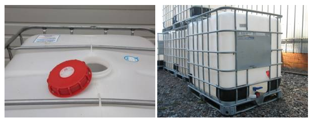
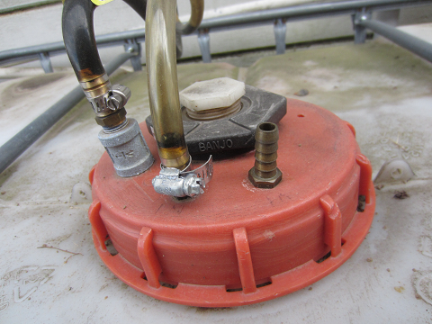
Notice the red plastic lid on the poly tank above. The lid is made from a fairly thick plastic. I drill 3 holes in the top of the lid for the following connections.
1. Fuel Feed (left)
3. Fuel Return (middle)
1. Vent/overflow (right - I still need to connect this before I use it.)
To create a Fuel Feed (to the pump on the burner), connect fittings for a 3/8" copper tube that runs from the lid to about 1" from the bottom of the tank when then lid is screwed on.
For the Fuel Return (from the pump on the burner) and the Vent/overflow, a 3/8" hose barb by 3/8" NPT fitting will work if you want to run a flexible hose for these lines. I use 3/8" I.D. clear poly tubing. This fitting will snugly self thread right into the plastic if you drill the correct hole size. The benefit of the clear poly tubing is I can see if the Fuel Return line is working and whether there is any overflow occuring in the Vent/overflow line. If the Vent/overflow line ever gets oil then you know you have a Preheat Tank float problem.
For the copper oil feed tube a brass fitting that has a compression fitting on one side (for the copper tubing) and a NPT thread on the other is used. The hole drilled in the plastic lid for this fitting is just big enough for the NPT threads to slide through and then its screwed into the galvanized coupler shown in the picture.
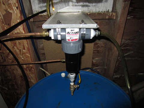
Optionally a 50 gallon drum could be added inside a building so that the oil gets warmed by the furnace and is not so cold to preheat during the winter. If you decide not to install the optional indoor tank, the 50 Mesh Stainless Steel filter will still need to be installed on the oil "feed" line.
Optional Indoor Tank
This tank is connected "in line" with the outdoor tank. With various valves, the optional tank can be filled, and the furnace run from just the inside tank or from the outside tank. Once the tank is filled, the outside tank can be shut off completed so that return oil goes to the inside tank.
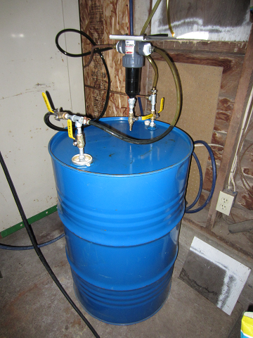
In the above setup, the valves are setup so that the furnace is being run from just this inside tank. Refer back to this photo after you learn more about the valves described below
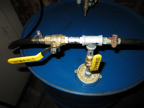
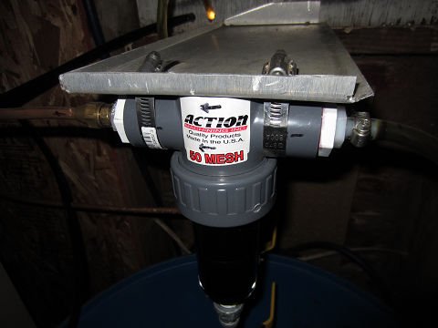
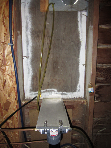
Notice the 50 Mesh Stainless Steel cleanable filter mounted above the tank. The main body is clear and thus it appears black with the oil in it. Notice the flow direction signals marked at the top of the filter. The upper copper tubing feeds oil directly to the burner's oil pump and the lower copper line is the oil return.
At the bottom of the filter is attached a valve and hose fitting so it the filter body can be drained for cleaning when necessary.
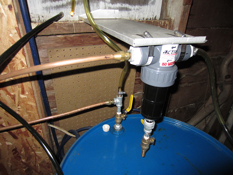
It the above photo you can see the valve (yellow handle) is in the "open" position. This allows the return oil to go into the barrel until it's full. Once the barrel is full the return oil will continue out the clear poly tubing and to the main outside tank. In the following picture you can see the ploy tube return line is looped up higher on the wall before comign back down the wall and ging outside. This was done so that if the valve is "open" on the barrel the weight of oil in the tube (due to a slight pressure from the pump) has to overcome gravity before it can return to the main tank. Otherwise, part of the oil may want to return to the outside tank instead of going into the inside tank. This gives me a clear visual indicator since the oil will get pushed up the tube by the pump when the inside tank is full.
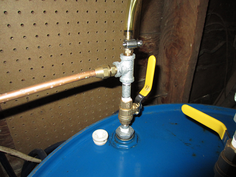
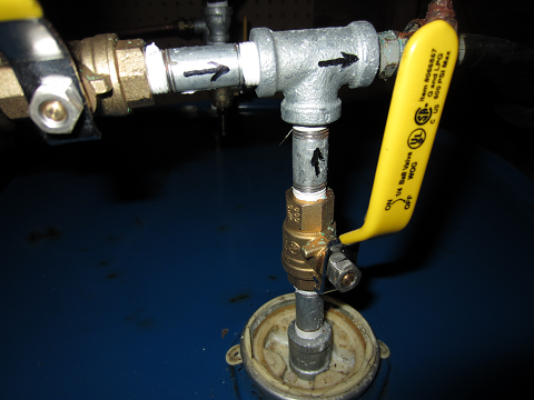
Here's a photo of the inside tank "feed" valves. With the top left valve in the "closed" position and the other in the "open" position, oil feed is coming only from this inside tank/barrel. Also, this tank/barrel has a copper tube that extends into the barrel to within about 1 inch of the bottom. This was done similarly as in the outdoor tank, except the white 2 inch bung hole plug (shown below) was removed and a hole drilled in it and adapted with similar fittings.
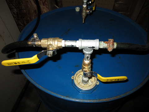
In the following configuration, the furnace oil comes from just the outside tank (left valve "open" and bottom right valve "closed"). Notice the poly tubing on the left is from the outside tank and the poly tubing on the right goes to the Mesh Filter.
In this next configuration both valves are open. The furnace can run from oil in the barrel while the barrel is filling. If the barrel is empty, you would not want to run the furnace while in this configuration because air would get sucked into the feed line. To fill the barrel "open" the left valve, "close" the bottom right valve and "open" the valve to the barrel on the return line.